60GHz Radar - GovTech Embedded Systems Internship
 05 Apr 2021 - Jeremy See
60GHz Radar: Embedded Systems Sensors
In the summer of 2020, I had the opportunity to intern at GovTech Singapore Sensors and IoT. During that period I worked on a proof of concept with cutting-edge 60GHz mmWave radar sensors.
What is mmWave Radar?
60GHz mmWave radar is a new type of sensor technology pioneered by Texas Instruments, by incorporating the entire radar front end in CMOS architecture, enabling an SoC design combining the RF front end, DSP for I/Q signal processing, and the CPU for general instructions.
In principle, what this radar does is send out a chirp, a specially modulated radio wave around its baseband frequency (60GHz), and “listen” for the reflected signal as it bounces off nearby objects. It’s similar to how you can shout into a large room and listen for the echo to determine how far parts of the room are from you. You can use the time delay between sent and receive pulses, as well as the beat frequency, sent through a Fast Fourier Transform (FFT) to determine the frequency of the received wave. This allows you to determine the Doppler and Signal-to-Noise ratio of the received signal, and subsequently, estimate position based on your radar’s coordinate axes.
This technology is commonly used in Autonomous Driving, as an all-weather solution to detecting surrounding obstacles. Thanks to its active nature of emitting its own sensory pulses, it is able to function in all light conditions and is relatively weather agnostic. In fact, it just happens to cover the weaknesses of computer vision (bad lighting conditions, sensitivity to weather, unable to gauge speed due to 2D nature). That makes radar a popular solution in the ADAS sensor market, alongside cameras. In fact, Elon Musk agrees with this, disparaging its competitor LIDAR for being too pricey.
System Architecture
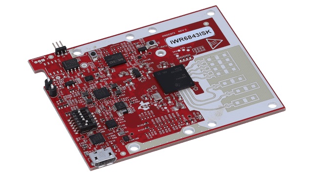
Interfacing with the IWR6843ISK radar module from TI was relatively straightforward using the standard UART interface: 8 data bits, no parity bit, and 1 stop bit. This allowed me to design and fabricate a custom PCB to control the radar module from an MCU, and pipe out the required data to a server for subsequent analysis and display on a dashboard.
Firmware
The firmware was written in C/C++, as required by the vendor toolchain for the MCU. I opted for FreeRTOS to write my code in a modular style, increasing visibility, and maintainability. However, this increased the difficulty of debugging to optimise memory usage to account for the high data throughput from the radar sensor, and subsequent processing done on the MCU. After unit testing on a basic testbench in the lab, we were able to move to field testing at the final deployment site, where we fine-tuned the sensitivity parameters of the radar to increase accuracy.
Machine Learning for Fall Detection
I tested a fall detection algorithm using a Variational Recurrent Autoencoder in Tensorflow to classify incoming data as a fall or not-fall. This model was chosen as a suitable unsupervised learning model for time-series data. The model was trained with in-house data of falls and tested in the same environment (ouch!). However, the model was only as accurate as a simple height-based algorithm due to the significant noise in the incoming data. Testing was done with a larger training set but minimal improvements were found, leading to the conclusion that richer incoming data was required to detect subtle patterns hidden in the noise.
Further Development: FPGAs
To further explore ways to take advantage of the high resolution of the radar sensor, I used an FPGA to receive data through the dual LVDS bus. In the extension to this project, I used Vivado to program the Zynq FPGA with an LVDS receiver. The received I/Q signals were sent through an FFT block to obtain the range-doppler response from the sensor.
Unfortunately, I wasn’t able to finish this extension during the course of my internship there, but this first encounter with FPGAs and programmable logic is something I’ll definitely be looking to explore in the future!